Water Pump Control Box Wiring Diagram
Occasionally, the wires will cross. Assortment of submersible pump control box wiring diagram.

Well Pump Switch Wiring Diagram Wiring Sample
Technicians should test a well pumps control box before pulling a nonworking pump from the well.

Water pump control box wiring diagram. This article describes and identifies the switches, controls, and safety devices used on water tanks and water pumps such as the pump pressure control switch, pump motor relays, water tank relief valve, water tank pressure gauge, water tank air volume control, and water tank air valve. How to wire a submersible pump controller. Injunction of 2 wires is generally indicated by black dot to the intersection of two lines.
Find your nearest retailer to shop today. Wiring diagram of water filling tank note: The junction box must insure dry,.
Control boxes are mounted outside near the well. Submersible pump control box wiring diagram for 3 wire single phase. Magnusrosen wp content 2018 08 goldsta.
Please switch 'water filling /water drainage' to 'water filling'. But, it does not mean link between the wires. Water pump wiring troubleshooting repair diagrams.
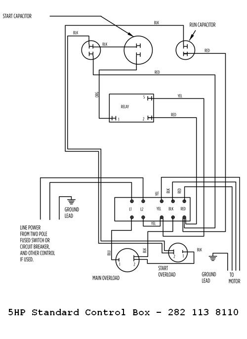
It shows the elements of the circuit as streamlined forms, […] Control boxes contain the starting circuits for well pumps. Before you star wiring the controller box switch must be in the off position.
44 luxury single phase submersible pump starter wiring diagram submersible well pump jet pump well pump. Red and yellow might indicate that it is a 2 wire 220 volt pump. Deep submersible well pumps will be either 2 wire or 3 wire well pumps and 3 wire well pumps will need a separately installed control box.
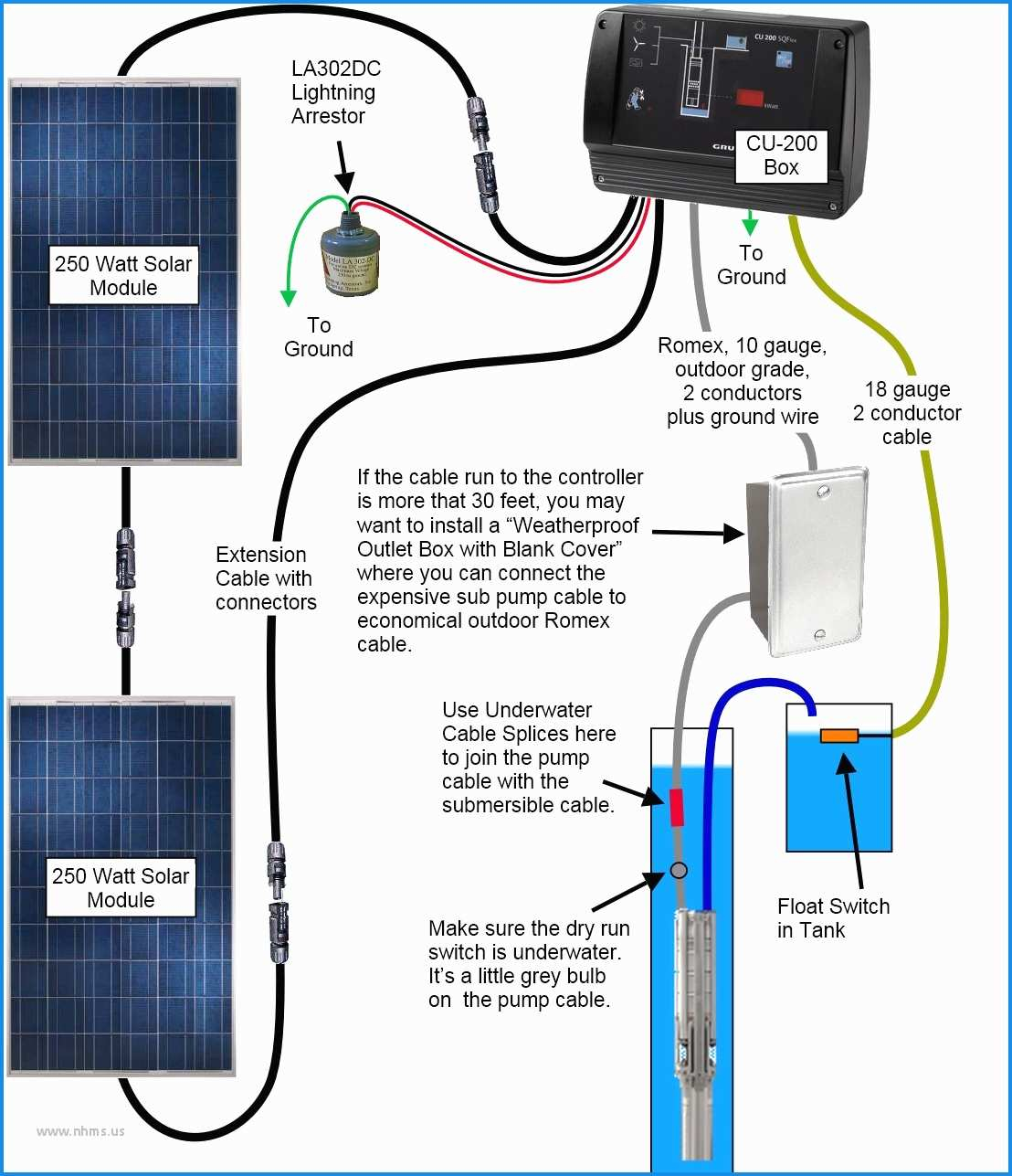
Many standard control panels come equipped with alarm circuits. Wiring diagram for pumps with 2 wires plus ground switch 10 20 30 40 50 60 70 80 tank control box to pressure to control box pump pressure switch ground wire (green) 4 in. Water pump controller with float switchauto manual connection of water pump motor w.
A double pole switch is the safest way to make sure that both lines of the 240 volt circuit power to the pump are turned off. The wiring connection of submersible pump control box is very simple. Green = ground blue = run brown = start black = common you will see that
Each component should be placed and connected with different parts in specific manner. Technicians should test a well pump's control box before pulling a nonworking pump from the well. Pump may show water stains as a result of factory water testing.
This video shows wiring a franklin submersible pump control box. Well id breaker box to pump wiring diagram for pumps with 3 wires plus ground note: The pumps the external control box for 4 wire v pumps may come with a 3 prong plug.
It shows the elements of the circuit as simplified forms and also the power as well as signal links between the devices. Water pump wiring diagram single phase. Otherwise, the structure won't function as it should be.
Sometimes the cables will cross. If so, you're not alone. 2 wire well pump diagrams are slightly easier to understand and are more straight forward to wire.
Automatic water level controller wiring diagram for 3 phase motor submersible pump submersible pump water. With this sort of an illustrative guidebook, you are going to have the ability to troubleshoot, prevent, and full your projects easily. As stated earlier, the traces at a water pump pressure switch wiring diagram represents wires.
Wiring diagram for 220 volt submersible pump bookingritzcarlton info in 2021 submersible well pump submersible pump submersible. Well pump & water pump controls: Make sure the pump and controller are not touching each other.
Control box wiring diagrams and other control relay. Single phase 3 wire submersible pump control box wiring diagram. The motor starts for pumping water while the water in the water filling tank goes below the mid level.
220v 3 wire well pump wiring diagram. If the wiring is incorrect, the pump will run backwards. Wire the solar pump and solar panels to the dc controller as per the wiring diagram.
The motor stops pumping while the water in the water filling tank reaches the high level, the low level probe works as loop.

Submersible Well Pump Wiring Diagram Gallery

Well Pump Control Box Wiring Diagram Automatic Water

Wiring Diagram For 220 Volt Submersible Pump, http
Submersible Pump Control Box Wiring Diagram For 3 Wire

Single Phase Submersible Pump Starter Wiring Diagram

Gallery Of Well Pump Wiring Diagram Sample

Wiring Diagram Of Control Panel Box Of Submersible Water Pump

Well Pump Pressure Switch Wiring Diagram at Wiring Diagram

Well Pump Wiring Diagram — UNTPIKAPPS
30 Tank Float Switch Wiring Diagram Wiring Diagram Database

Lead Lag Pump Control Wiring Diagram Free Wiring Diagram

Well Pump Switch Wiring Diagram Wiring Sample

Submersible Motor Control Box Wiring Single Phase water

Wiring Of Flotec Well Pump Diagram Wiring Diagram Schemas

Submersible Well Pump Wiring Diagram Gallery

How To Test Well Pump Capacitor

Submersible water pump control box wiring diagram������ YouTube
Water Pump Control Box Wiring Diagram Complete Wiring
![]()
Wiring Diagram Of Control Panel Box Submersible Water Pump